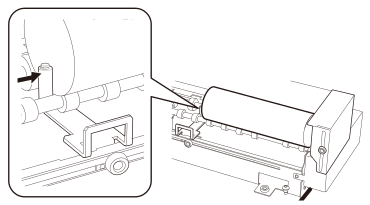
Attaching the Object to Be Printed on
-
Measure the diameter of the objects to be printed on.
Write down the measured result. Enter the result that was measured in Performing Printing.
-
Prepare to attach the objects to be printed on.
Rotary axis unit
-
When loading objects to be printed on that have a diameter of 10 to 35 mm (0.39 to 1.37 in.)
Attach a small-diameter adapter and the short guide to the rotary axis unit.
Attaching the Small-diameter Adapters
Attaching the GuideMEMOTemporarily tighten the short guide's screw.
Adjust the height of the short guide when you place the objects on the rotary axis unit.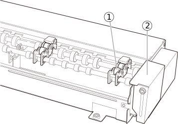
-
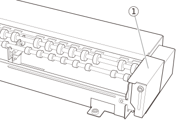
When loading objects to be printed on that have a diameter of 35 to 75 mm (1.38 to 2.95 in.)
Attach the short guide .
Attaching the GuideMEMOTemporarily tighten the short guide's screw.
Adjust the height of the short guide when you place the objects on the rotary axis unit.
-
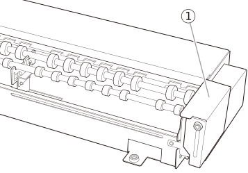
When loading objects to be printed on that have a diameter of 75 to 115 mm (2.96 to 4.52 in.)
Attach the long guide .
Attaching the GuideMEMOTemporarily tighten the long guide's screw.
Adjust the height of the long guide when you place the objects on the rotary axis unit.
Object to be printed on
If the objects to be printed on are transparent, shield them.
For the shielding methods, see Shielding the Object to Be Printed on from Light.
If the objects are opaque, shielding is not necessary.MEMODetermine whether the objects are transparent or opaque according to the following standard.- Transparent: A hand placed on the other side of the object to be printed on can be seen through it.
- Opaque: A hand placed on the other side of the object to be printed on cannot be seen through it.
-
-
Place the object on the rollers of the rotary axis unit.
Place the object to be printed on according to the guide.
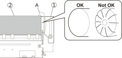
Gently bring the object to be printed on into contact with the left edge of the guide .MEMO- Rotation may be impeded if the object to be printed on forcefully pushes against the guide, leading to defective printing. Attach the object to be printed on so it touches the guide gently.
- Make sure that edge A of the object to be printed on, which touches the guide, is perpendicular to the print surface and is a flat, even surface. If a rough surface that is not flat touches the guide, the object to be printed on will move to the left and right, leading to misalignment in the printing position and other such reductions in quality.
- Media with the following shapes cannot be placed on the rotary axis unit.
- Any media that does not have a cylindrical shape
- Media with an undulating surface that affects rotation
-
Adjust the height of the guide.
Adjust the guide so that the distance, b, from the highest position on the object to be printed on to the top of the guide is 2 mm (0.08 in.).IMPORTANT
When tightening the guide's retaining screw, push the guide against the rotary axis unit to prevent the guide from tilting.
After tightening the retaining screw, check that the guide is not tilted. If you tighten the screw without pushing the guide against the rotary axis unit, distance b may be different.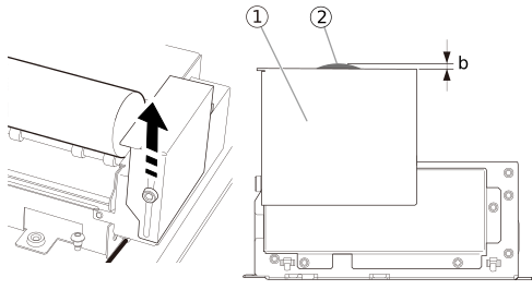 MEMO
MEMOAfter the guide height adjustment is complete, once more check that the object to be printed on is gently touching the guide.
Rotation may be impeded if the object to be printed on forcefully pushes against the guide, leading to defective printing.
-
Attach the tail stopper.
Use the tail stoppers when printing around the entirety of a cylinder, when printing layered colors, and in similar situations. Gently bring the tail stopper into contact with the object to be printed on to prevent it from moving left or right, and then tighten the mounting screw.
IMPORTANTThe tail stoppers cannot be used when:-
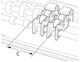
The object to be printed on is shorter than the width C of the small-diameter adapters attached next to each other.
- The outer diameter of the object to be printed on, such as a bottle, differs on its left and right ends, making it impossible to touch the tail stopper to the object.
- A tail stopper is placed outside of the range covered by its slide hole.
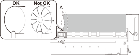
MEMO- Rotation may be impeded if the tail stopper forcefully pushes against the object to be printed on, leading to defective printing. Attach the tail stopper so it touches the object to be printed on gently.
- Make sure that edge A of the object to be printed on, which touches the tail stopper, is perpendicular to the print surface and is a flat, even surface. If a rough surface that is not flat touches the tail stopper, the object to be printed on will move to the left and right, leading to misalignment in the printing position and other such reductions in quality.
-
If the object to be printed on has undergone embossing, place the object so its embossed part does not touch the roller of the rotary axis unit.
If the right edge of the object to be printed on cannot be brought into contact with the long guide or short guide, remove the long or short guide and attach tail stoppers.
You can only place tail stoppers at the right edge or both edges of the object to be printed on when this object is opaque.
When tail stoppers are placed at the right edge or both edges of the object to be printed on, the length of the object that can be placed is reduced.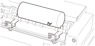
-