
2. Setting the Object to be Printed On for the First Time
An overview of the procedure for setting the object is as follows. Follow the instructions displayed on the screen and perform the work in sequence.
- Select the object shape type and color, and then enter the dimensions of the object.
- Attach so that the center of the object and the rotation axis of the rotary device are aligned.
- Set the printing area and printing reference point in order to specify the printing location.
- If the object shape type is irregular, measure its ridge line.
Procedure
- Select New and tap Next.
-
Enter a name, tap OK, and then tap Next if the name is correct.
To make corrections, tap the name you entered.
-
Select the shape type of the object and tap Next.
Shape type Description Cylindrical A three-dimensional object which can be fully rotated using one side of the rectangle as the axis Conical Here, a truncated cone (three-dimensional object that can be fully rotated using the center line of the trapezoid as the axis) and a cone (three-dimensional object that can be fully rotated using one side of the right angle in a right triangle as the axis) are both referred to together as "conical." Irregular Here all rotating bodies which are not cylindrical or conical are referred to as "irregular." This is intended for shapes such as a cup with a slightly narrowed end or a bottle with a narrow pouring opening. - Select the opacity of the object and tap Next.
-
Enter the dimensions of the object.
Measure the dimensions of the object, and enter the diameter and length. The items to be entered vary depending on the shape type.
Tap
 for each item to display the entry screen. Enter the value and tap OK.
Shape type Description Cylindrical Enter the diameter [D] and length [L]. 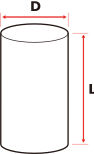
Conical Enter the diameter of the larger end [D(L)], diameter of the smaller end [D(S)], and length [L]. 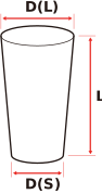
Irregular Enter the diameter of the larger end [D(L)] and the length [L]. 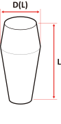
-
When entry of the object dimensions is completed, tap Next.
The support table will move to where the object is loaded.
-
Open the light shield cover and place the object on the support table.
When the object has a conical shape or other shape where the diameter is not constant, place it so that the side with the larger diameter is on the right side. If it is placed with the smaller diameter on the right side, printing will not be possible.
Place the object so that its right edge is a few millimeters to the left of the jig on the right side.
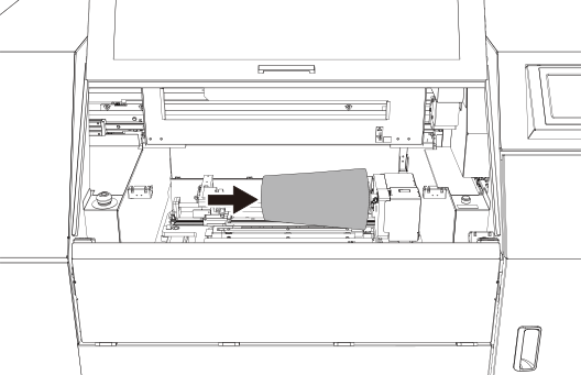
-
Tap Next.
The Media Loading Adjustment window appears.
-
Correctly load the object onto the rotary device.
- Align the rotational center axis of the rotary device with that of the object to reduce eccentricity.
- Ensure an appropriate distance between the print surface of the object loaded on the rotary device and the bottom surface of the print head (ink discharge surface).
- To prevent the object from deforming when held, ensure an appropriate force when the rotary device grips the object.
-
Tap the left or right raise/lower buttons (
 or
or  ) to adjust the height of the support table.
-
Tap the Table Height raise/lower buttons ( or ) to adjust the height of the print surface.
Adjust the object so that the print surface extends about 2 mm (0.08 in.) above the top of the light shield cover.
-
Tap the Rotary Device Angle Adjustment raise/lower buttons ( or ) to adjust the tilt of the rotary device.
-
Perform operations according to the on-screen instructions.
If this step is not necessary, tap Next without performing any operations.
- Close the light shield cover if it is open.
-
When Irregular is selected for the shape type, tap Measurement on the Ridge Line Measurement screen.
The undulations of the profile of the object are measured. When the measurement is completed, tap Next.When Cylindrical or Conical was selected for the shape type, this procedure is not displayed. Skip it and proceed to the next step.
-
Set the printing area and reference point.
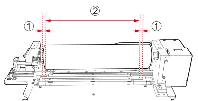
The maximum printing area is as follows.
-
12.5 mm (0.49 in.; []) to the inside from the left and right sides of the irradiation window of the UV-LED device. This area is indicated with .
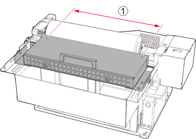
- For models with the UV-LED device located in front of the support table:
The maximum printing area is , the area to the inside from the alignment holes on the left and right sides of the top of the UV-LED device.
-
Tap
 or
or  .
The pointer moves.
.
The pointer moves. -
Tap or to move the pointer and set the right edge of the printing area.
-
Tap or to move the pointer and set the length from the right edge of the printing area.
-
Tap .
The pointer moves.
-
Tap or and the rotate button on the rotary device ( or ) to move the pointer to the printing reference point.
-
-
Tap Measurement.
The head gap is measured, and the results are displayed on the screen.
Adjust Table Height and Rotary Device Angle Adjustment (with
or ) to make Min 3 mm (0.12 in.). - After configuring the settings, tap Next.
-
Attach the light blocking sheet to the light shield cover in the gap between the loaded object and the irradiation window of the light shield cover.
Prevents UV light from passing through the gap. This operation is unnecessary if there is no gap.
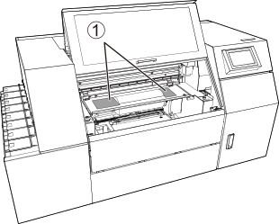 MEMO Use scissors to cut the light blocking sheet to fit the size of the gap.
 -
For models with the UV-LED device located in front of the support table, adjust the position of the UV-LED device.
-
Hold on the UV-LED device and move the UV-LED device forward or backward so that the distance between the object and the UV-LED device is about 5 mm (0.2 in.) at the closest point.
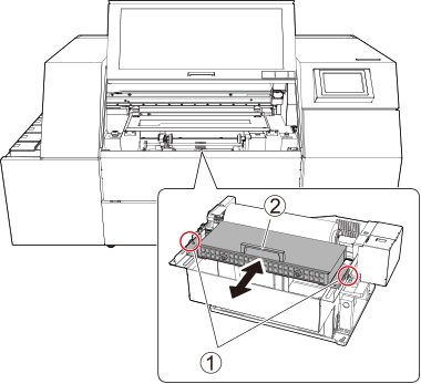
-
Hold on the UV-LED device and move the UV-LED device forward or backward so that the distance between the object and the UV-LED device is about 5 mm (0.2 in.) at the closest point.