
Creating a Fixing Jig for the Object
A fixing jig is a fixing device for efficiently setting a particular object onto the output device.
For example, if the object is concave, it will be possible to only set objects for printing that fit into the jig.
Printing can be made simply by removing the printed product and replacing it with a new object without performing setup or print positioning each time, greatly improving productivity. Use of a fixing jig has advantages when the product created using the fixing jig is expected to cover the time and cost of creating the jig.
It is possible to set a fixing jig with the same specifications as the actual jig in PAM (where it is referred to as the "jig"), allowing print data to be pasted into it for efficient printing. This section explains the procedure for creating a virtual fixing jig (jig) in PAM.
- Start the Web browser and access the following URL.
-
Log in to PAM-Web.
Log in using a PAM account and password, not Roland DG Connect.
- Enter the URL to access in Your environment name.
- Enter the user account name in User name.
- Enter the password in Password.
- Click Log in.
-
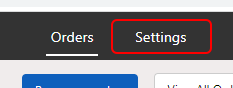
Click Settings.
-
Click Jigs.
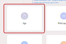 The Available Jigs display appears.
 -
Click New Jig.
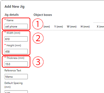
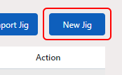 The Add New Jig display appears.
 -
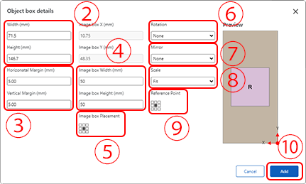
Enter the jig size and thickness according to the fixing jig design drawing (dimensions drawing).
-
Set the object and the print image.
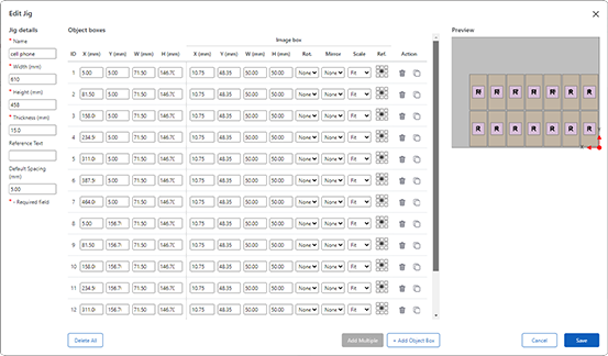
This explains the procedure for jig specifications where multiple of the same object are arranged on the fixing jigs and printing is performed all at once.
-
Click Add Multiple.
The Object box details display appears.
-
Click Add Multiple.
-
Click
 under Location.
The Select Locations display appears.
under Location.
The Select Locations display appears.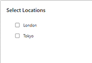
Select the location to place this jig, and click OK.
-
Click under Printer Type.
The Select Printer Types display appears.
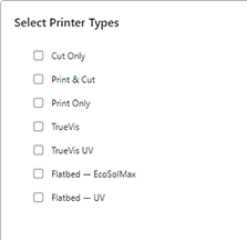
Click a printer type where this jig can be installed to select it, and then click OK.
-
Check the settings again, and then click Add.
Copy an Object box and position each copy at the set distance with one copy on each jig.
-
Click Save.
Follow the same procedure and register all jigs.