
Setting Reports
There are multiple settings that you can change to customize job reports. To change these settings, click , and then scroll down to the area below the General Settings area.
Scroll down a little bit to find the Report section.
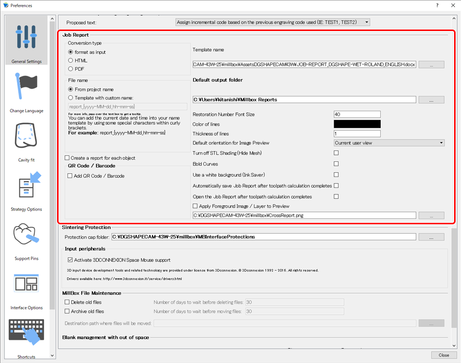
Conversion type
- format as input
A file format used as a report template is saved. In other words, if you are using a MS Word template file, an MS Word file is output (with the same extension).
- HTML
The job report is output in HTML format for viewing in a web browser.
- PDF
The job report is output in .PDF format for reading in Adobe Reader/Acrobat.
File Naming Template
Use the From project name setting to select whether to set the file name to a name associated with the project (the naming convention in the default settings) or to a custom name. The usable codes are shown below.
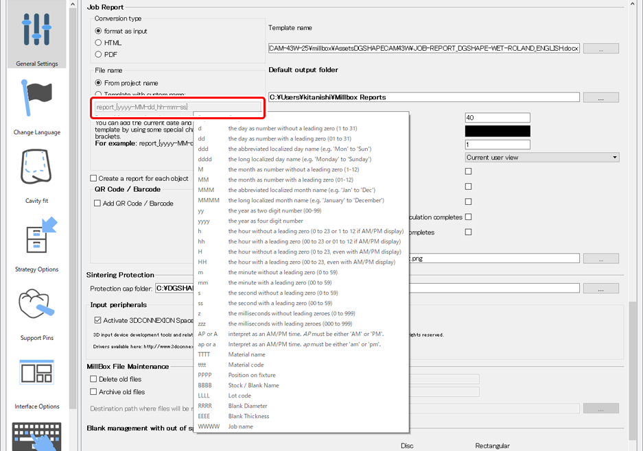
- report_{yyyy-MM-dd_hh-mm-ss}
report_2020-01-09_17-46-25
- DGSHAPE CAM_{tttt-OOOO-EEEE}_{yyyy-MM-dd}
DGSHAPE CAM_zr-18-CIMSYSTEM_2020-01-09
Select job report base file
This is the location of the job report template, which is used as the foundation for the report format and the way to enter information into the report.
- .DOC (requires Microsoft Office)
- .ODT (requires OpenOffice, free software made by the Apache Software Foundation)
- .RTF (requires WordPad, free software installed on Windows-based PCs; limited format settings)
Save job report in
This is the location where job reports are saved with the default settings.
Report image cell size
You can customize the font size in the default settings for the number used to identify the dental prosthesis in the stock/blank. (The default setting is 40, but you can adjust this value according to increases/decreases in size of the dental prosthesis contained in the blank.)
Line color
You can customize the color of lines printed in the report.
Line thickness
The default setting is 1.
Image Preview Orientation
You can customize the method used to display the image of the placed dental prosthesis in the job report by selecting this method from the drop-down menu. With the default settings of most installations, the view/orientation set with the layout area is recorded in the job report. You can select the following additional options for uniform, easy-to-read job report output.
Current user view
Initial settings
Simply records the current layout view as the job report preview.
Top down, 100 mm × 100 mm (3.94 in. × 3.94 in.)
An image with dimensions of 100 mm × 100 mm (3.94 in. × 3.94 in.) and seen from the top is created. When job reports are created, images are always shown from the top regardless of the orientation selected by the user.
Bottom up, 100 mm × 100 mm (3.94 in. × 3.94 in.)
An image with dimensions of 100 mm × 100 mm (3.94 in. × 3.94 in.) and seen from the bottom is created, allowing you to check the inner surface of the dental prosthesis. When job reports are created, images are always shown from the bottom regardless of the orientation selected by the user.
Object mesh (hide mesh)
You can hide the mesh (the rendered image) of the dental prosthesis, displaying only the curves/straight lines.
Mark object curve
Draws the curve with a thick, black line.
Background (saving ink)
Use this function to print the job report on a white background, saving ink and, depending on the location on the page, improving visibility.
Automatically save report after calculation
Open report after calculation
Use background image
You can set the image to layer on top of the layout image of the recorded job report. With the default settings, you can use a .PNG file with a red cross. This image is useful for separating the area into four quadrants to identify the positions of dental prostheses. You can freely specify the image, but be sure to use a transparent .PNG image. If you use another type of image, the layout image may be completely covered.