
Kinematic simulation
Opening the Simulation Tool
The Kinematic simulation tool can be executed from within DGSHAPE CAM after the toolpath calculation finishes.
Use the following procedure to start this tool.
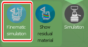
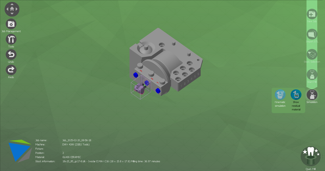
- Select Simulation.
-
Click Kinematic simulation to open the simulation tool.
 When you execute the Kinematic simulation tool, the following window appears, allowing you to check the status of the simulation being run.
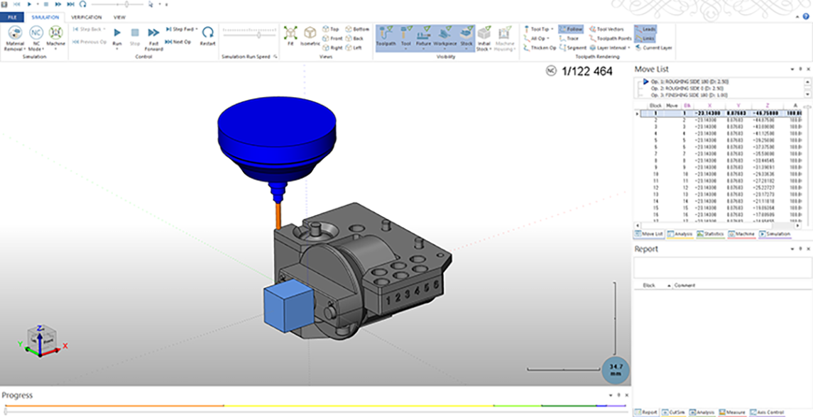
You can use this tool to simulate the calculated toolpath and check the virtual cutting of the material in the window.
Controlling the Simulation Tool/Simulation Tool Shortcuts
Rotate

Pan

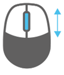
Zoom
Operating the Simulation Tool
The simulation tool has various areas, as follows.
Playback Controls/Simulation Speed
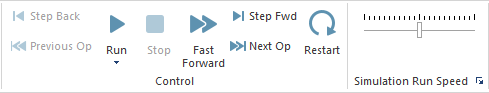
These tools are used to play back the simulation being executed and to control the speed of this simulation.
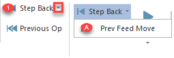
- Step Back/Prev Feed Move:
Click the down arrow to display the "Prev Feed Move" options.
- Step Back:
Moves back one step in the code text.
- Prev Feed Move:
Ignores rapid movements and returns to cutting.
- Step Back:
- Previous Op:
Returns to the start of the previous toolpath milling operation.
- Run:
Starts the simulation.
- Stop:
Stops the simulation.
- Fast Forward:
Progresses the simulation (the speed depends on "Simulation Run Speed").
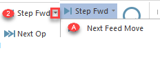
- Step Fwd/Next Feed Move:
Click the down arrow to display the "Next Feed Move" options.
- Step Fwd:
Proceeds one step to the next row in the text.
- Next Feed Move:
Ignores rapid movements and proceeds to the next cutting and milling operation.
- Step Fwd:
- Next Op:
Proceeds to the next toolpath milling operation in the simulation.
- Restart:
Restarts the simulation from the beginning.
- Simulation Run Speed:
There is a slider to the right of this label. Drag this slider to the right of the center line to increase the simulation run speed and to the left of this line to decrease this speed.
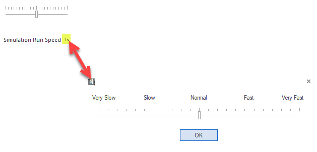
You can drag the "Simulation Run Speed" slider to the left and right to change the speed of the simulation.
Click the box in the lower-right corner to display the run speed in a pop-up window.
View
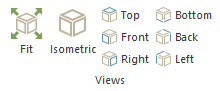
Fit

Moves the fixture/dental prosthesis to the center of the current position.
Isometric

Returns the fixture/dental prosthesis to its original position.
Top/Front/Right

- Top:
Switches to a view showing the fixture/dental prosthesis from the top.
- Front:
Displays the front of the fixture/dental prosthesis. (Side view)
- Right:
Displays the right side of the fixture/dental prosthesis. (Side view)
Bottom/Back/Left

- Bottom:
Displays the bottom of the fixture/dental prosthesis.
- Back:
Displays the back of the fixture/dental prosthesis. (Side view)
- Left:
Displays the left side of the fixture/dental prosthesis. (Side view)
Display Tools
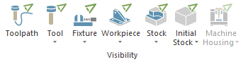
- Tool:
This is the cutting bur. Use this icon to switch the display of the generated cutting bur.
- Fixture:
This tool is used to secure the target dental prosthesis during milling with the milling machine.
- Workpiece (target dental prosthesis):
Use this icon to switch the display of the fixture/source .STL file.
- Stock (material being processed):
This is the material being milled with the milling machine to reach the model of the workpiece. Use this icon to switch the display of the material to cut.
- Initial Stock:
This is the initial material supplied to the milling machine.
- Machine Housing:
This is a group of parts that does not affect the kinematics of the milling machine.
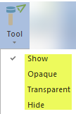
This function uses the following settings.
- Show:
Uses the standard setting specified with the transparency setting in the milling machine definitions xml file.
- Opaque:
Sets the transparency of the shape to 0%.
- Transparent:
Sets the transparency of the shape to 50%.
- Hide:
Sets the transparency of the shape to 100% (the shape is completely hidden).
- Toolpath:
A toolpath is the path of the cutting bur. This setting shows/hides all the created toolpaths. Toolpaths may obstruct the simulation, so it is best to hide such toolpaths before starting the simulation.
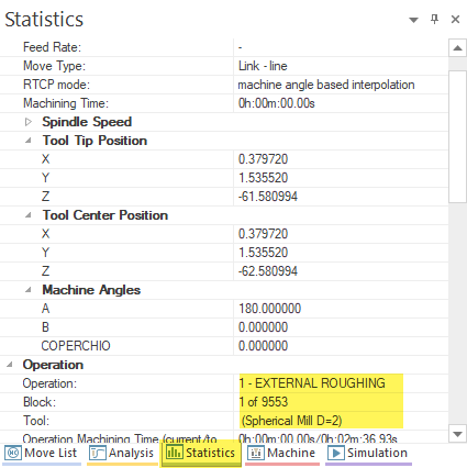
Statistical Data
Statistical information related to the milling being executed or simulated is displayed in this area of the simulation tool.
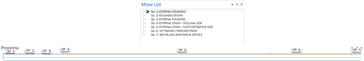
Move List
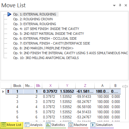
You can use this list to easily perform programming, move within a program, and quickly move to the process being executed during cutting.
Just select the desired milling operation in the list to move to this operation. The simulation tool must perform the simulation within the specified permissible range, but this takes time, so note that there are points that may take time to catch up to when they are selected in the program.
Statistics
Measurement
If you shorten the simulation and proceed, you will not check for collisions that occur within the simulation tool. To simulate collisions, you have to execute the simulation to completion without interruption (you can increase the simulation speed).
Simulation - Remaining Cutting
You can use this window to display the remaining cutting with a color map that indicates thickness.
Progress Bar
If you shorten the simulation and proceed, you will not check for collisions that occur within the simulation tool. To simulate collisions, you have to execute the simulation to completion without interruption (you can increase the simulation speed).