
Correcting the Misalignment of Printing and Cutting with Crop Marks (Concurrent Test for Printing and Cutting with Crop Marks)
Depending on the composition of the media, the positioning of printing and cutting may be misaligned even when you are using crop marks. Make corrections for misaligned printing and cutting for the media you are using.
In cutting with crop marks, cutting is performed after removing the media after printing. However, with this method, you can make corrections of printing and cutting positions at the same time without removing the media.
1. Adjust the misalignment of the ink landing position.
-
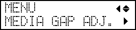
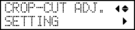
Press [▼] several times to display the screen shown below.
-
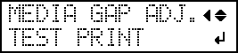
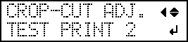
Press [▶] to display the screen shown below.
-
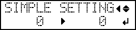
When printing is finished, press [▼], then [▶] to display the screen shown below.
-
View the printed test pattern, and then determine the correction value.
Select the value that gives the least misalignment between the two lines. In the case of the following figure, select "-3." When you cannot choose between two sequential numbers, select a value that is between them (you can set correction values in units of "0.5").

-
Press [◀] or [▲] to display the screen shown below.
-
Check the test pattern to see whether the correction was successful.
Check that the misalignment is minimized for the two vertical lines indicated by
 (that is, the current correction value). If the misalignment is smaller for another set of vertical lines, set the correction value again.
2. Correct the misalignment of printing and cutting with crop marks at the same time.
-
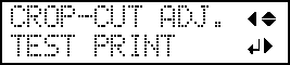
Press [▲] to display the screen shown below.

-
Press [▶], then [▼][▶] to display the screen shown below.
-
Check the test pattern (C&C1) condition.
Check whether the printing position (shaded part) and the cutting position (outer frame) are aligned. An example of the printing position and the cutting position being misaligned is shown in the following figure."F" indicates the feed direction of the media (the feed direction) and "S" indicates the direction of print head movement (the scan direction).

If the printing position and the cutting position are aligned, no corrections are necessary.If the printing position and the cutting position are not aligned, proceed to the next procedure.
-
Press [▼] twice to display the screen shown below.
-
Press [▲] to display the screen shown below.
-
Check the correction values from the test pattern (C&C2) condition.
The point where the cutting line (
 ) intersects the correction-value scale (
 ) is the correction value. In the following figure, the correction value is "−0.3."
Check the media feed direction (the feed direction) and the direction of print head movement (the scan direction).

-
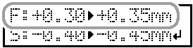
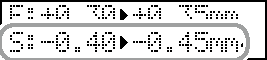
Set the correction values for the feed direction "F" and the scan direction "S."
-
Press [▲] or [▼] to set the correction value for the feed direction (F).
-
Press [◀] or [▶] to set the correction value for the scan direction (S).
-
Press [▲] or [▼] to set the correction value for the feed direction (F).
-
Press [MENU], then [▲] to display the screen shown below.