
Step 2: Automatically Correcting the Cutting Position
Required item
| Included item | ||
|---|---|---|
 |
 |
 |
| Rotary axis correction jig | Mounting screw | ATC magazine correction jig / screw A |
 |
 |
 |
| Detection pin for correction | T-shaped hexagonal screwdriver | Cloth for care |
Handle the detection pin for correction and the dummy pin separately to be absolutely sure that you do not confuse them.
If the detection pin for correction is used as the dummy pin even once, the detection pin for correction cannot be used to provide proper correction. If for some reason the detection pin for correction is used as the dummy pin, a new detection pin for correction will be necessary.
Contact your authorized DGSHAPE Corporation dealer or access our website (https://www.dgshape.com/).
1. Perform automatic correction.
- Close the front cover if it is open.
- Show VPanel.
-
Click
 .
.
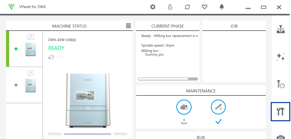
The Machine settings window is displayed.
-
On the Maintenance tab, click Automatic correction.
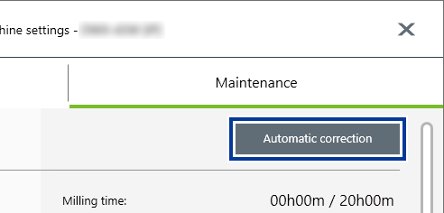
-
Click Next.
Follow the on-screen instructions to perform automatic correction.
2. Clean the detection location for use during correction.
-
Open the front cover.
Hold the parts shown in the figure below with both hands and open the cover.

-
Remove all milling burs set in the ATC magazine.
CAUTION
Be careful around the tip and other sharp edges.
Be careful not to touch the tool tip or any other sharp edges. Doing so may cause injury.
MEMOIf a milling bur is difficult to remove, use the milling bur removal jig.
Insert the tip of the milling bur into the tip (the narrow end) of the milling bur removal jig, and then push the milling bur up to remove it.

-
Use the cloth for care to wipe off dirt from the gray locations shown in the following figure.
If any dirt is present in these locations, it may not be possible to perform the correction properly.

3. Attach the automatic correction jig.
-
Attach the ATC magazine correction jig to the rotary axis unit.
Align the holes on the ATC magazine correction jig with the protrusions on the rotary axis unit, and then use the A screw () to secure these parts.

-
Attach the rotary axis correction jig to hole "2" on the rotary axis.
-
Align the recessed portion of the jig with the protrusion on the rotary axis, and then push the jig in.
Ensure that there is no gap between the surfaces. It does not matter which of the two recesses on the jig is aligned to the protrusion.

-
Use a T-shaped hexagonal screwdriver to secure the rotary axis correction jig in place with a mounting screw.

-
Align the recessed portion of the jig with the protrusion on the rotary axis, and then push the jig in.
- Close the front cover.
- Click Next.
4. Install the detection pin.
Remove the dummy pin from the collet, and then attach the detection pin for correction.
-
Open the front cover.
Hold the parts shown in the figure below with both hands and open the cover.
-
Using your hand, hold the dummy pin attached to the collet.

-
Hold down the operation button and remove the dummy pin from the collet.
Holding down the operation button opens the collet. Pull the dummy pin out slowly to prevent it from falling into the machine.

-
After removing the dummy pin, temporarily place it in a safe location.

- Click Next.
-
Insert the detection pin for correction into the collet, hold the pin in place, and then hold down the operation button.
Insert the pin all the way to the back, ensuring that there is no gap between the surfaces. The collet closes, grasping the detection pin for correction.

-
Close the front cover.
The rotary axis unit will move to a position that makes the next step easier to carry out.
- Open the front cover.
-
Insert the removed dummy pin () all the way to the back of the dummy pin stocker.
The tapered (slanted) end is the top of the dummy pin. Be careful not to confuse which side is up and which is down.
IMPORTANTPay attention to the position where the dummy pin is inserted.
Inserting the dummy pin into a stocker in the wrong position may lead to collisions during operation, causing a malfunction.

-
Check the items displayed in the window.
Check all the items, and select their checkboxes.
- Click Next.
-
Close the front cover.
The automatic correction starts. The automatic correction is finished when the operation complete message is displayed.
5. Remove the detection pin and the automatic correction jig.
-
Open the front cover.
Hold the parts shown in the figure below with both hands and open the cover.
-
Remove the rotary axis correction jig.

-
Remove the ATC magazine correction jig and the detection pin for correction.

- Close the front cover.