Be sure to perform operations as specified by the instructions, and never touch any area not specified in the instructions.
Sudden movement of the machine may cause injury or burns.
CAUTION
To prevent damage to the device and electrical shock, only insert and remove the rotation shaft unit connector when the main power is off or when executing [Insert/remove optional unit] from the utility.
MEMO
Use the following link to view a reference video for this procedure. We recommend that you view this video to understand the overall flow of work.
If the printer has not been set up, refer to the "Installation Guide" and "Installation and Initial Settings" linked to below to perform printer setup and install the printer software.
The sub power is switched on. When the sub power button indicator changes from flashing blue to steady blue, startup is finished.
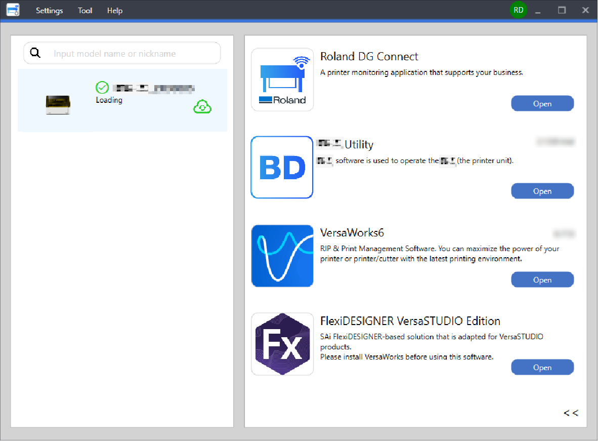
Start Utility from the Roland DG Connect Hub home screen.
Click Open next to Utility.
Click on the Utility window.
Click Preferences.
Click Execute under Rotary Unit Attachment/Removal.
The flat table moves to a position where the rotary axis unit can be attached.
After the flat table stops moving, open the front cover and the maintenance cover.
Open the maintenance cover according to the procedure below.
Hold the underside of the maintenance cover, and pull it approximately 30 mm (1.18 in.) towards you.
Lift the maintenance cover up to remove it.
Attach the rotary axis unit positioning screws to the flat table using the included hexagonal wrench.
Attach the machine to the flat table.
CAUTION
Exercise caution to prevent the rotation shaft unit from falling.
Failure to do so may result in injury.
Place the machine on the flat table.
Have the machine come into contact with the rotary axis unit positioning screws, as shown in the figure.
With the machine touching the rotary axis unit positioning screws, align the holes on the machine and the flat table threaded holes as shown in the figure.
Attach the rotary axis unit fixing screws.
Connect the connector on the machine to the printer on the printer side.
Pass the machine cable through the slit on the flat table.
Connect the connector on the machine to the printer on the printer side.
Align the protruding part on the connector, and insert it firmly until you hear a click.
Click Next on the Utility window.
Attach the maintenance cover according to the following procedure.
Insert the hooks (B) on the maintenance cover into the grooves on the left and right (A).
Secure the maintenance cover in place using the magnets (C).
Close the front cover.
Click Finish on the Utility window.
If the connector is properly connected, the illustration in the Utility window will change to the rotary axis unit.This completes the machine installation procedure.
If this is your first time installing the machine, adjust the position of the manual cleaning tool.


 on the Utility window.


