
Changing Media Settings in a Batch
- Start the Batch Media Settings.
- Set up the media whose settings you will change.
- Tap
 .
. - Tap .
- Change the Heater Temperature.If you will not change it, tap Save and Proceed.
- Check that Heater Power is turned on (
 ).
). - Tap
 or
or  to change the Front Heater temperature.A temperature that is too high may degrade the media or cause it to wrinkle.
- Check that Heater Power is turned on (
- Change the Print Head Height.If you will not change it, tap Next.
- Move the height-adjustment lever to change the print head height.
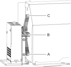
Position Operation panel display Description A Low Normally set the height-adjustment lever to Low. B Medium For media that is wrinkled or comes loose from the platen during printing, set the height-adjustment lever to Medium. C High For media that is wrinkled or comes loose from the platen during printing even when the height-adjustment lever is set to Medium, set the lever to High.
- Move the height-adjustment lever to change the print head height.
- Change the Media Suction Force.If you will not change it, tap Save and Proceed.
- Tap or to change the value.
0 to 100% When the media is flimsy and cannot move smoothly, such as with thin films, decreasing this value (reducing the suction force) may correct the problem. Auto The suction force is automatically adjusted to the optimal level for the media width.
- Tap
- Change the Media Sticking Prevention.This setting is used to peel off the media before starting printing when using media that sticks easily to the platen. This setting is effective to prevent media jams. Note, however, that peeling off the media may cause unstable media feed. Leave this menu item set to Disable unless you specifically need to change it.
If you will not change it, tap Save and Proceed.
- Select Enable or Disable.
- Tap Save and Proceed.
- Change the Middle Pinch Auto Raise/Lower.Change the setting that causes the middle pinch rollers to go up automatically during pullback printing or printing and cutting.
If you will not change it, tap Save and Proceed.
- Select Enable or Disable.
- Tap Save and Proceed.
- Change the .
If you will not change it, tap Next.
- Tap .
- Tap
 .
. - Tap
 ,
,  , or
, or  to move the center of the blade to the position that you want to set as the base point.
 - Once the position has been decided, tap Set Base Point Here.
- Tap Next.
- Change the Detailed Feed Correction (Manual).Perform corrections to make the band-shaped "stripes" on the printed surface less noticeable.
If you will not change it, tap Save and Proceed.
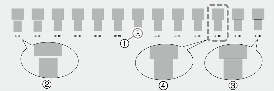
- Check the printed test pattern, and then tap or to change the correction value.The current correction value is that of the figure indicated by "
 ." Select the value to make the gap and overlap between the upper/lower squares smallest. In the case of the following figure, select "−0.40." (). When you cannot choose between two sequential numbers, specify a value that is between them.
  MEMO
MEMO- If the test pattern is difficult to see, tap or next to Media Feed to move the media to a position where it is easier to see.
- If you want to hold the media to check the test pattern, tap Execute next to Sheet Cutting to separate the media.
- If the test pattern is difficult to see, tap
- Check the test pattern to see whether the correction was successful.Check that the gap and overlap are the smallest for the figure indicated by "" (that is, the current correction value). If the gap and overlap are smaller for another figure, set the correction value again.
- Check the printed test pattern, and then tap
- Change the Detailed Media Gap Adjustment (Manual).This adjusts the landing position of the ink discharged from the print heads.
If you will not change it, tap Save and Proceed.
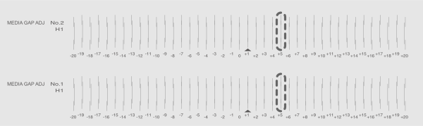
- Check the printed test pattern, and then tap or to change the No. 1 and No. 2 H1 correction values.Select the value that gives the least misalignment between the three lines. In the case of the following figure, select "+5" for H1 of No. 1 and No. 2. When you cannot choose between two sequential numbers, select a value that is between them (you can set correction values in units of "0.5").
 MEMO
MEMO- If the test pattern is difficult to see, tap or next to Media Feed to move the media to a position where it is easier to see.
- If you want to hold the media to check the test pattern, tap Execute next to Sheet Cutting to separate the media.
- If the test pattern is difficult to see, tap
- Check the test pattern to see whether the correction was successful.For all the correction values, check that the misalignment is minimized for the three vertical lines indicated by "" (that is, the current correction value). If the misalignment is smaller for another set of vertical lines, set the correction value again.
- Check the printed test pattern, and then tap
- Configure the Blade Adjustment.You can accurately set items such as the blade force, movement speed, and blade offset to match the nature of the media and the shape to cut.
If you will not make adjustments, tap Save and Proceed.
- Check the results of the cutting test.Check that the two shapes are peeled off separately, a blade trace (red line) remains on the backing paper, and the backing paper is not cut.

Check item Result Setting item Adjustment Check the shape. The cut shape is distorted. Cutting Speed Reduce Peel off the circle. The square also peels off. Blade Force Increase Some uncut areas remain. Cutting Speed Reduce Peel off the square. The blade leaves faint traces on the backing paper. Blade Force No change The blade trace is indistinct. Increase The blade trace is too deep and cuts into the backing paper. Reduce Check the shape of the square you have peeled off. 
The corners are not rounded and do not have "horns." Blade Offset No change 
The corners are rounded. Increase 
The corners have "horns." Reduce - Tap or to change the settings.
Setting item Setting details Default setting Blade Force Set the force (pressure) of the blade. 50 gf (0.11 lbf) Cutting Speed Set the speed of cutting. 30 cm/s (11.81 in./s) Blade Offset Set the blade offset. Enter the listed offset value for the blade.
The offset value for the included blade is 0.250 mm (9.8 mil).
0.250 mm (9.84 mil) Rise Movement Speed Set the blade's up speed during cutting (the speed at which the blade travels when it moves to the next cutting line after cutting one cutting line). If the media comes loose during no-load feed and the blade damages the surface of the media, reduce the speed. 30 cm/s (11.81 in./s)
- Check the results of the cutting test.
- Configure the Multi Sensor Adjustment.Depending on the characteristics of the media, such as reflectivity and colors, the machine may not be able to read the media width. In such cases, correct the sensor for reading the media.
If you will not make adjustments, tap Next.
- Configure the Print & Cut Position Adjustment.This is a correction method performed when printing followed immediately by cutting yields positioning for printing and cutting that is slightly misaligned.
If you will not make adjustments, tap Save and Proceed.
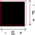
- Check the result of Printing Test 1.Check whether the printing position (shaded part) and the cutting position (red line) are aligned. An example of the printing position and the cutting position being misaligned is shown in the following figure.
F indicates the feed direction of the media (the feed direction) and S indicates the direction of print head carriage movement (the scan direction).
 If the printing position and the cutting position are aligned, no corrections are necessary. Tap Save and Proceed.
If the printing position and the cutting position are not aligned, proceed to the next procedure.
- Check the correction values from the Printing Test 2 condition.
The point where the cutting line (A) intersects the correction-value scale (B) is the correction value. In the following figure, the correction value is "−0.3."
Check the media feed direction (the feed direction) and the direction of print-head carriage movement (the scan direction).
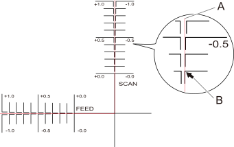
- Set the correction values in the feed direction of the media (the feed direction) and the direction of print-head carriage movement (the scan direction).
- Tap or next to Correction Value (Feed) to set the correction value in the feed direction of the media (the feed direction).
- Tap or next to Correction Value (Scan) to set the correction value in the direction of print head carriage movement (the scan direction).
- Tap
- Tap Execute next to Printing Test 1
(Misalignment Check).Printing Test 1 is printed and cut. If the printing and cutting lines are aligned, adjustment is complete. If further adjustment is needed, tap or next to Correction Value (Feed) and Correction Value (Scan) to fine-tune the printing and cutting position, and then Save the values.
- Check the result of Printing Test 1.
- Configure the Crop Cut Position Adjustment.
Use the following procedure to print the crop marks and cut the media, checking for misalignment in the positions. In this section, a cutting test is performed after the crop marks are printed, without removing the media.
So as to create the same conditions as the actual operation, you can also perform a Separate Test for Printing/Cutting with Crop Marks in which you print only the crop marks, remove the media, load the media again, and then cut the media. For information on this setting method, refer to Correcting the Misalignment of Printing and Cutting with Crop Marks (Separate Test for Printing and Cutting with Crop Marks).
If you will not make adjustments, tap Save and Proceed.
- Tap next to Separate Test for Printing/Cutting with Crop Marks to turn it off.
- Check Printing Test 1.Check whether the printing position (shaded part) and the cutting position (red line) are aligned. An example of the printing position and the cutting position being misaligned is shown in the following figure.
F indicates the feed direction of the media (the feed direction) and S indicates the direction of print head carriage movement (the scan direction).
If the printing position and the cutting position are aligned, no corrections are necessary. Tap Save and Proceed.If the printing position and the cutting position are not aligned, proceed to the next procedure.
- Check the correction values from the Printing Test 2 condition.
The point where the cutting line (A) intersects the correction-value scale (B) is the correction value. In the following figure, the correction value is "−0.3."
Check the media feed direction (the feed direction) and the direction of print-head carriage movement (the scan direction).
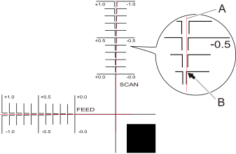
- Set the correction values in the feed direction of the media (the feed direction) and the direction of print-head carriage movement (the scan direction).
- Tap or next to Correction Value (Feed) to set the correction value in the feed direction of the media (the feed direction).
- Tap or next to Correction Value (Scan) to set the correction value in the direction of print head carriage movement (the scan direction).
- Tap Save.
The correction values are saved.
- Tap
- Tap Execute next to Printing Test 1
(Misalignment Check).Printing Test 1 is printed and cut. If the printing and cutting lines are aligned, adjustment is complete. If further adjustment is needed, tap or next to Correction Value (Feed) and Correction Value (Scan) to fine-tune the printing and cutting position, and then Save the values.
- Tap
- Change the Over Cut.Set it to Enable to allow the corners of the border of the cutting line to be cut slightly longer so that the corners can be cut attractively.
If you will not change it, tap Save and Proceed.
- Tap Enable or Disable.
- Tap Save and Proceed.
- Change the Printing Movement Range.This shortens output time by reducing the width of print-head carriage movement to the minimum necessary. This is effective when the width of the media or the output data is narrow.
If you will not change it, tap Save and Exit.
- Tap
 .You are returned to the home screen.