6 Correct the misalignment of the printing and cutting positions.
-
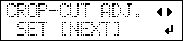
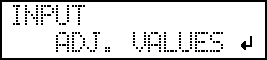
Press ◀ to select SET.
-
Check the test pattern (P&C1).
Check whether the printing position (shaded part) and the cutting position (outer frame) are aligned. An example of the printing position and the cutting position being misaligned is shown in the following figure.
"F" indicates the feed direction of the media (the feed direction) and "S" indicates the direction of print head movement (the scan direction).

-
Determine whether to correct the misalignment.
- Cutting position and printing position are not aligned
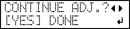
Press ◀ to select YES.
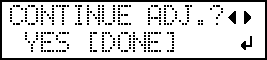
- Cutting position and printing position are alignedPress ▶ to select DONE.
- Cutting position and printing position are not aligned
-
Press ENTER.
-
Check the correction values from the test pattern (P&C2) condition.
The point where the cutting line (
 ) intersects the correction-value scale (
 ) is the correction value. In the following figure, the correction value is "−0.3."
Check the media feed direction (the feed direction) and the direction of print head movement (the scan direction).

-
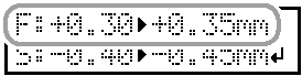
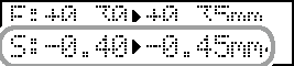
Set the correction values for the feed direction "F" and the scan direction "S."
-
Press ▲ or ▼ to set the correction value for the feed direction (F).
-
Press ◀ or ▶ to set the correction value for the scan direction (S).
-
Press ▲ or ▼ to set the correction value for the feed direction (F).
-
Determine whether to correct the misalignment.
- Cutting position and printing position are not aligned
Press ◀ to select YES.

- Cutting position and printing position are alignedPress ▶ to select DONE.

- Cutting position and printing position are not aligned
-
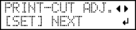
Press ▶ to select NEXT.