Understanding Curves/Surfaces and Types of Dental Prostheses
This page explains the important curves and surfaces that are necessary for efficiently applying strategies to the dental protheses placed in DGSHAPE CAM. This explanation summarizes the required and optional curves and surfaces for each object type.
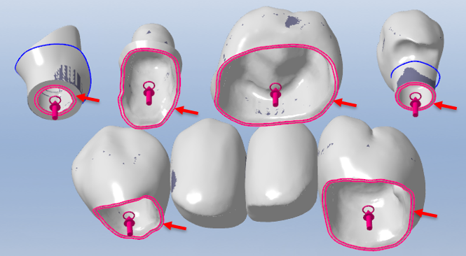
Margin Line/Prep Line
- Color: Pink
- Type: Curve
Displayed locations:
Cavity vicinity/accurately above margin lines
Application
This item differentiates the internal and external milling in the strategy. It indicates the correct direction in which to cut the internal cavity (the pink arrows and circles) to allow for the acquisition of the intended results in internal cutting.
Optional or required
Required for objects that have a cavity
You can hide the pink arrows with circles, but they are always shown if there is a margin line.
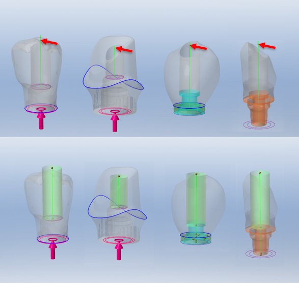
Hole Axis
- Color: Green
- Type: Curve
Displayed locations:
Center part of cylinders that require drilling/center part of screw channels
Application
This item indicates the cylinder used in drilling.
Optional or required
Required for objects that have a screw channel or cylindrical hole
Emergence Profile Curve
- Color: Blue
- Type: Curve
Displayed location:
Edge of emergence area
Application
Delimits the end of the emergence area (the green area).
Optional or required
Optional
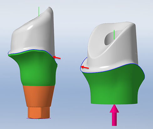
Emergence Profile Area
- Color: Green
- Type: Surface
Displayed locations:
Abutment margin line or between the identification section and the emergence profile curve (blue curve)
Application
To obtain high-quality surfaces, apply a different strategy to this area.
Optional or required
Optional

Cylinder Cap
- Color: Red
- Type: Layer
Displayed locations:
Cylinders/screw channel start point and end point (not present in cavities)
Application
The cylinder cap covers the cylinder entrance, preventing the tool from entering the screw channel access hole during rough milling and finish milling.
Optional or required
Required for objects that have a screw channel or hole
This can be hidden (shortcut key: [Ctrl] + [R]).
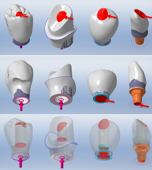
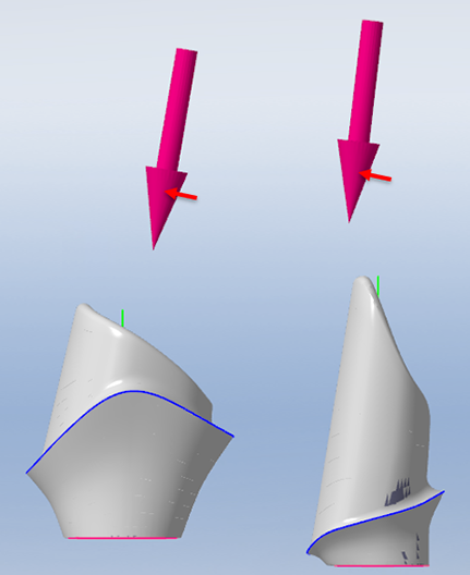
Cavity Axis
- Color: Pink
- Type: Arrow
Displayed locations:
Abutment, hybrid abutment, bur top
Application
Indicates the finish direction for the abutment top cap.
There should be no screw-retained crowns (having anatomical structures) handled in this manner.
Optional or required
Optional but strongly recommended for abutments, hybrid abutments, and burs.
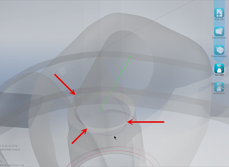
Screw Channel Profile (Angled)
- Color: Purple
- Type: Curve
Displayed locations:
Base of the angled screw channel of various implants or along the screw channel profile
Application
This item indicates the boundaries of drilling and hole finish milling.
When milling using an angled screw channel in DGSHAPE CAM, the cylindrical hole becomes elliptical or oval shaped.
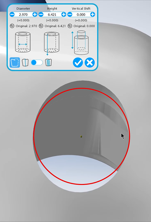
For details on how to place this curve, see Drone Cylinder.
Optional or required
Required when there is an angled screw channel
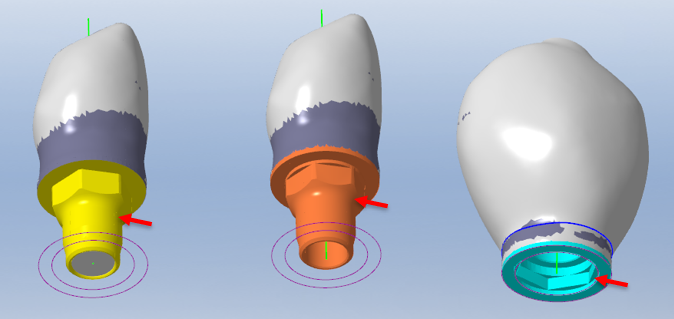
Identifying the Interface
- Internal junction: Orange
- External junction: Blue
- Replaced/Specified junction: Yellow
- Type: Interface/Junction
Displayed locations:
All junctions/interfaces on appropriately identified implants
Application
Shows junctions/interfaces on implants to allow for appropriate milling.
Optional or required
Required for abutment and implant objects