
Correcting the Misalignment of Printing and Cutting with Crop Marks at the Same Time
Use the following procedure to print the crop marks and cut the media, checking for misalignment in the positions. In this section, the crop marks are printed simply, and then the crop marks are read and a cutting test is performed without removing the media.
To simulate the actual process—printing crop marks, removing the media, and then performing post-processing such as laminating—before loading the media and checking for cutting position misalignment, turn on Correcting the Misalignment of Printing and Cutting with Crop Marks (Separate Test for Printing and Cutting with Crop Marks [Media Removed]).
Use the following link to view a reference video for this procedure. We recommend that you view this video to understand the overall flow of work.
https://youtu.be/kMajrYm5exs
The BN2-20/20A is shown in this video, but the work and operation procedures are the same for this machine.
-
Click
 .
.
-
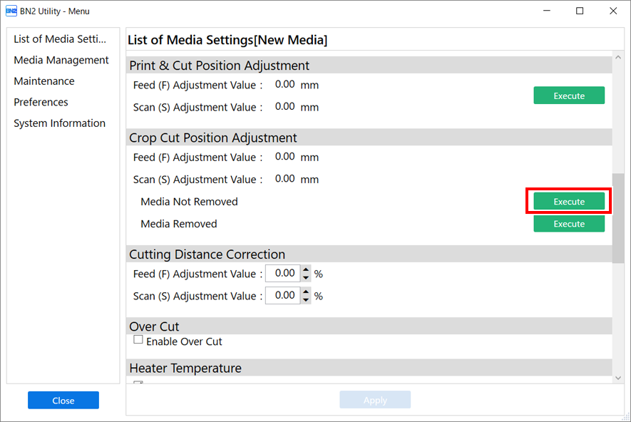
Click Execute under .
-
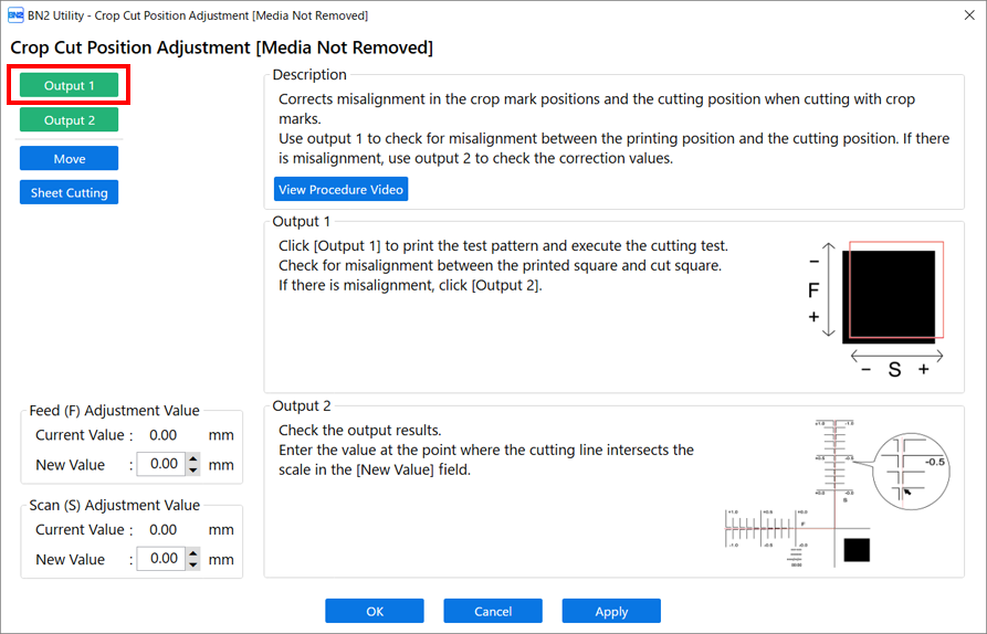
Click Output 1.
The machine prints and cuts the test pattern. View the printing result, checking for misalignment in the printing position and cutting position.
-
If the printing and cutting positions are misaligned
To determine the correction values, carry out the steps for Output 2. Proceed to step 4.
-
If the printing and cutting positions are not misaligned
This completes the Crop Cut Position Adjustment. Click OK to return to the original screen.
-
-
Click Output 2.
The machine prints and cuts the test pattern.
-
Check the correction values from the Printing Test 2 condition.
The point where the cutting line (A) intersects the correction-value scale (B) is the correction value. In the following figure, the correction value is "−0.3."
Check the media feed direction (the feed direction) and the direction of print-head carriage movement (the scan direction).

-
Read the on-screen description and enter each value next to New Value.
-
Feed (F) Adjustment Value: −2.00% to 2.00% (in units of 0.01%)
- Enter the value at the point where the Output 2 horizontal cutting line intersects the scale.
-
Scan (S) Adjustment Value: −2.00% to 2.00% (in units of 0.01%)
- Enter the value at the point where the Output 2 vertical cutting line intersects the scale.
-
-
Click Apply.
The values entered for New Value under Feed (F) Adjustment Value and Scan (S) Adjustment Value are applied to Current Value.
-
Click Output 1 again.
The machine prints and cuts the test pattern again.
-
If the printing and cutting lines are aligned, adjustment is complete. Click OK to return to the original screen.
-
If further adjustment is needed, change the Feed (F) Adjustment Value and Scan (S) Adjustment Value values to fine-tune the printing and cutting position.
When the adjustment is finished, click OK to return to the original screen.
MEMO-
Default settings
- Feed (F) Adjustment Value (correction value of the media feed direction): 0.00 mm
- Scan (S) Adjustment Value (correction value of the print-head carriage movement direction): 0.00 mm
- Depending on the changes in the condition of media caused by laminating and the loading position of the media before cutting, the positioning of cutting may be misaligned. In such cases, correct the misalignment of printing and cutting with crop marks.
-