
Step 2: Placing and Setting Up the Object
You can keep the front cover open when you set the height of the flat table, the print origin, or other settings for a closer view as you work.
However, clicking OK with these settings configured may cause the print-head carriage or flat table to start moving. Therefore, when the front cover is open, be careful not to touch any moving parts as you work.
- Start Utility.
-
Prepare a jig that ensures a printing area of about 30 mm × 30 mm (1.18 in. × 1.18 in.).

A: Approx. 30 mm (1.18 in.) B: Approx. 40 mm (1.57 in.) C: Approx. 100 mm (3.94 in.) -
Place the object.
-
Set up the object.
-
On the Utility home screen, click
 Setup.
-
Click
 .
MEMO In Utility, "media" is used on the window used to register/manage objects.
.
MEMO In Utility, "media" is used on the window used to register/manage objects.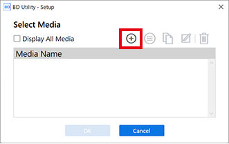
-
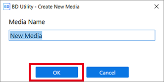
Enter the name of the object, and then click OK.
Previously registered media names cannot be used. Enter a new media name.
-
Click Change next to Flat Table Height to set the height of the object.
- Click
 or
or  on the right side of the window to align the highest point of the object with the forward-back position of the head gap sensor.MEMO You can select 0.1 mm (0.004 in.), 1 mm (0.04 in.), 10 mm (0.39 in.), or 50 mm (1.97 in.) as the single-click moving distance.
 - Click on the left side of the window to have the highest point of the object approach the head gap sensor.Move the highest printing position of the object up to a position (a) a few mm away from the head gap sensor without coming into contact with the head gap sensor.

- Click Automatic Setup.
The flat table moves and the head gap sensor detects the height of the object.
- Click OK.
- Click
-
Select Center Relative in Print Origin, click Change, and then set the printable area.
MEMO When the Printing Area setting is finished, the print-head carriage returns to its original position after it has been left in the same position for approximately 3 minutes to prevent the print heads from drying out. Perform the procedure again.Specify the Printing Area with the node of the golf ball as the Print Origin.
- Select Pointer for Position Specification.
The print-head carriage and the flat table move, and then the pointer on the right side of the print-head carriage illuminates the center of the maximum printing area.
- Select Printing Area.
The print-head carriage and the flat table move, and then the pointer illuminates the upper left of the maximum printing area.
- Click , ,
 , or
, or  , and then move the pointer to change the Printing Area to the print data size.
- The print-head carriage moves in the left-right direction and the flat table moves in the forward-backward direction.
- If you narrow the printing area, you will be able to move the center position.
- Select Center Position.
- Click , , , or , and then move the pointer to specify the node of the golf ball (the center of the printing area).The print-head carriage moves in the left-right direction and the flat table moves in the forward-backward direction. The position that the pointer illuminates serves as the center of the printing area.

- Make sure that the width and length of the Printing Area are the same as the print data size.
- Click OK.
Returns to the Flat Table Height, Print Origin, and Printing Area settings window.
- Select Pointer for Position Specification.
-
On the Utility home screen, click
-
Click OK.
Setup in progress. is displayed. When setup is completed, you are returned to the home screen, and the registered object name, and the set Flat Table Height, Print Origin, and Printing Area are displayed.