
System Configuration Diagrams
The image below shows the data flow from creating a design in Roland DG Connect Designer to printing on the machine.
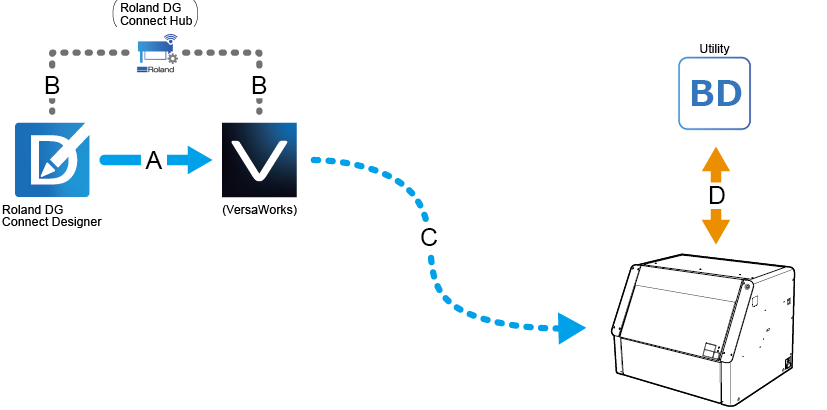
| A | Drafting data transmission |
| B | Drafting data transmission support |
| C | Printing data transmission |
| D | Operating and setting the machine |