
Create a Cutting Line From Shapes Included in the Print Data

-
Use one of the methods below to display the Job Assistant window.
- Right-click on the job to set, then click Job Assistant.
- Click on the menu bar.
-
Click
 .
.
-
Click to select the path or image that will be the basis of the cutting line.
- When the desired shape cannot be selected: Hold down the ctrl key while clicking the desired shape. This will allow multiple overlapping shapes and shapes within shapes to be selected.
- When selecting multiple shapes: Hold down the shift key and click on the desired shapes.
- To cancel a selection: Click on a blank location where there is no object.
-
Select the editing method
 .
.
-
Select Type of Cut from the following.
 : Cut
: CutCuts solid lines over the cutting lines that were created.  : Perforated Cut
Cuts perforated (broken) lines over the cutting lines that were created. -
Select the following conditions for Create Cutting Line.
Type of Contour  : Outline
Creates cutting lines based on the outline of the selected image. This will ignore any clipping mask.

 : Clipped Outline
If the selected image has a clipping mask, cutting lines will be created based on the outline of the part that is not masked. If the selected image does not have a clipping mask, it creates a cutting line in the same manner as Outline.

 : Bounding Box
Creates a rectangular cutting line around the selected image.

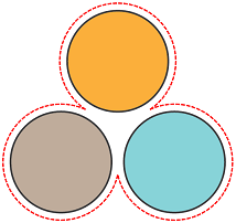
Cut Interior  : Cut Interior
If there are outlines on the inside of the selected image (as in the figure at top right), or you have selected multiple images and outlines can be made on the inside of adjacent images (as in the figure at lower right), a cutting line will be created on the inside.


 : Do Not Cut Interior
Even if there are outlines on the inside of the selected image (as in the figure at top right), or you have selected multiple images and outlines can be made on the inside of adjacent images (as in the figure at lower right), a cutting line will not be created on the inside.

Corner Shape  : Miter
Creates a cutting line that maintains the corner shape.
Note, however, that if Miter Limit is on, the cutting line will be chamfered depending on the angle.

 : Round
Creates a cutting line that rounds the corners.

 : Bevel
Creates a cutting line that chamfers the corners.

Miter Limit (Enabled only when Miter is selected for Corner Shape.) Off Creates a cutting line that maintains the corner regardless of the angle.
On Chamfers the corners according to the Angle settings.
Angle (Enabled only when Miter Limit is on.) Use the slider to set the Angle to be chamfered. The more you set the angle to the Large direction, the wider will be the angle at which chamfering is performed.

offset Sets the distance from the outline of the selected shape at which to create the cutting line.

-
Click Create.
The created cutting line is displayed. Solid lines are displayed in pink, and broken lines are displayed in gray.
- Click OK.
-
In the confirmation window, click Yes.
The Job Assistant window closes. It will be added to the job list as a new job.