
Adjusting the AAS Offset
If a shift has been found as a result of an AAS offset test, adjust the deviations in the width and length.
Procedure
-
Measure how much the cutting line () shifted using the printed lines () as a reference.
Figure 1. AAS offset test result - Line parallel to the material-feed direction (): X
- Line perpendicular to the material-feed direction (): Y

-
Press [MISC].
If material is loaded, press [ON/OFF LINE] to switch to offline mode.
-
Press [▶] several times to display the screen shown below.
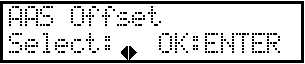
- Press [ENTER].
-
Press [▶] to move the cursor to X or Y, and then enter the offset value using [▲] or [▼].
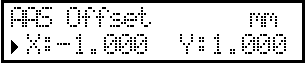
If the result is shifted to the positive direction, enter a negative offset. If the result is shifted to the negative direction, enter a positive offset. In the case of (A) in the sample AAS offset test result above, -1.00 is entered as the value for both X and Y. - Press [ENTER].
- Press [ON/OFF LINE] to go back to the original screen.
- Run an AAS offset test again.