Placing an Object (Crown) on a Pin/Block
Procedure-based Explanations
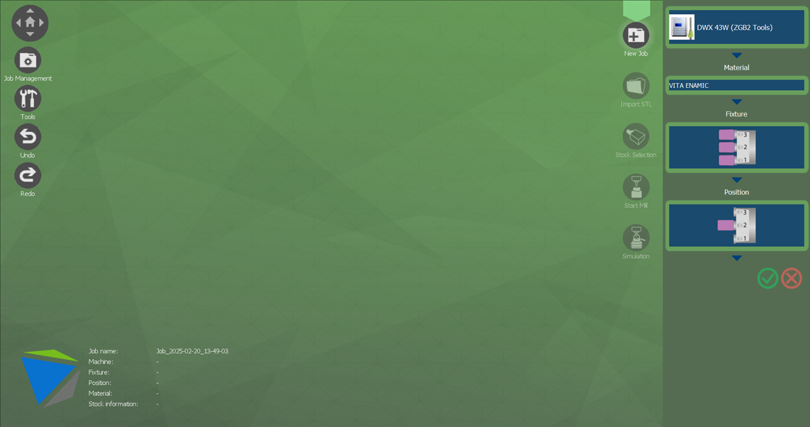
New Job
- Click New Job.
- Select the milling machine to use.
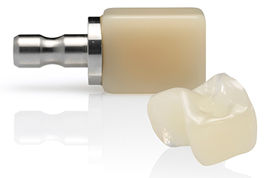
- Use Material to select the material (Pmma, VITA ENAMIC, etc.).
- Use Fixture to select the fixture to use.
- Use Position to select the planned position in which to attach the block.
-
Click the check mark to continue.
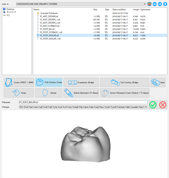
Importing an Object
- Select one .STL file to import.
- Select the dental prosthesis type for classification.
-
Click the check mark button to proceed to the next step.
 MEMO
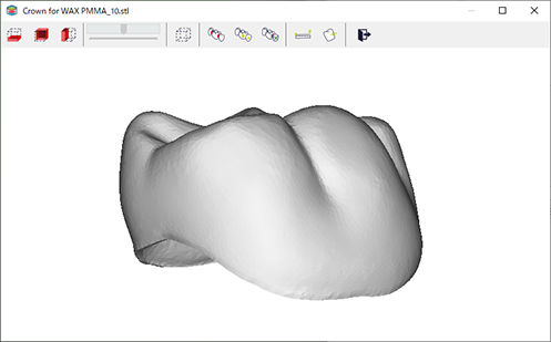
MEMOA preview of the selected .STL file is displayed at the bottom of the window. Click the image to display a separate pop-up window in which you can rotate and zoom in on the preview.
When the dental prosthesis is imported, a message prompting you to perform the next operation is automatically displayed in CAM.
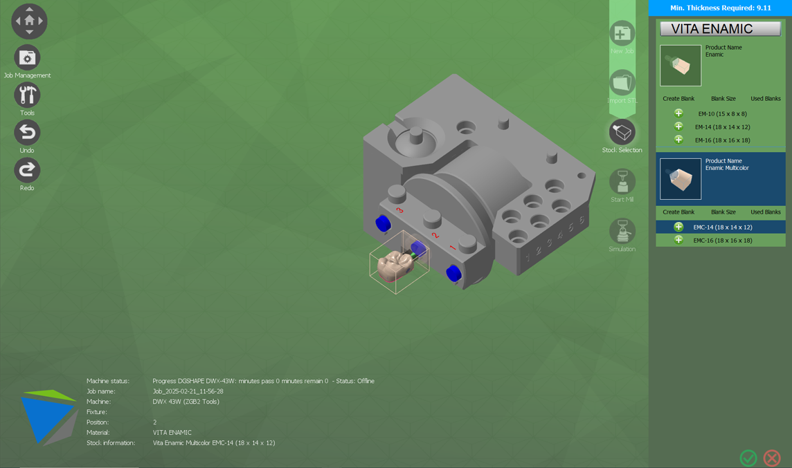
Selecting the Material
-
Check whether the dental prosthesis fits in the material.
If the material is smaller than the dental prosthesis, the parts that project outside the material are displayed in red. This is useful in judging in which block the dental prosthesis fits.
- Select the green + (plus) mark next to the new blank to use.
-
Select the check mark to continue.
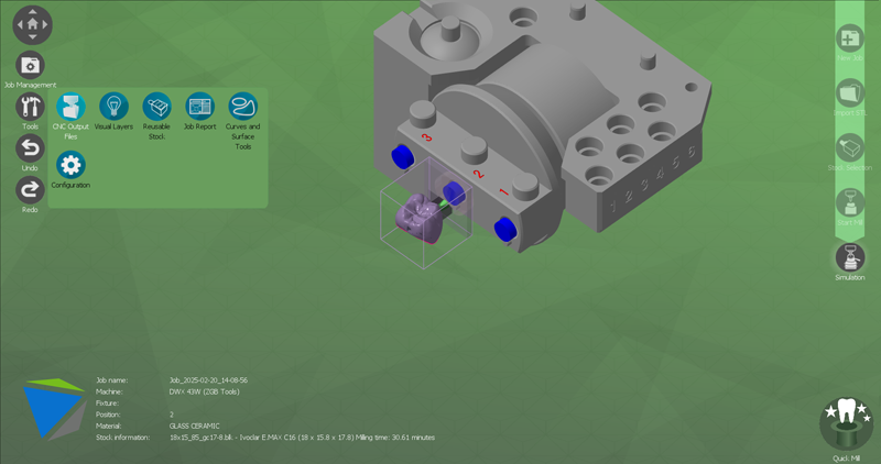
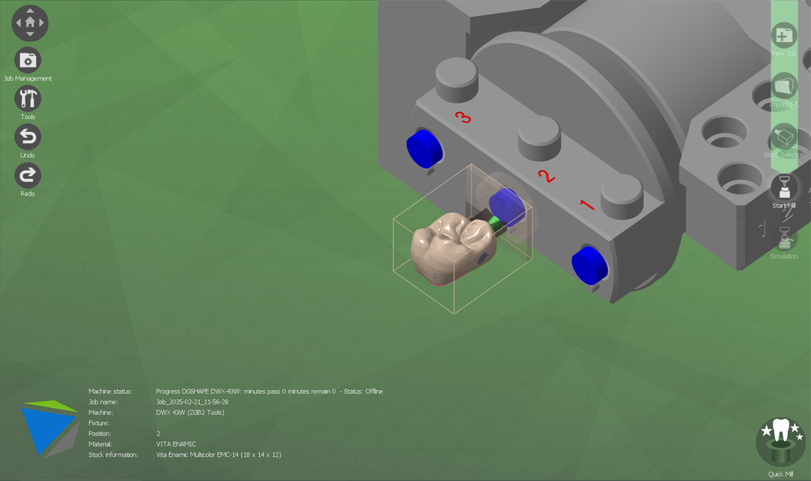
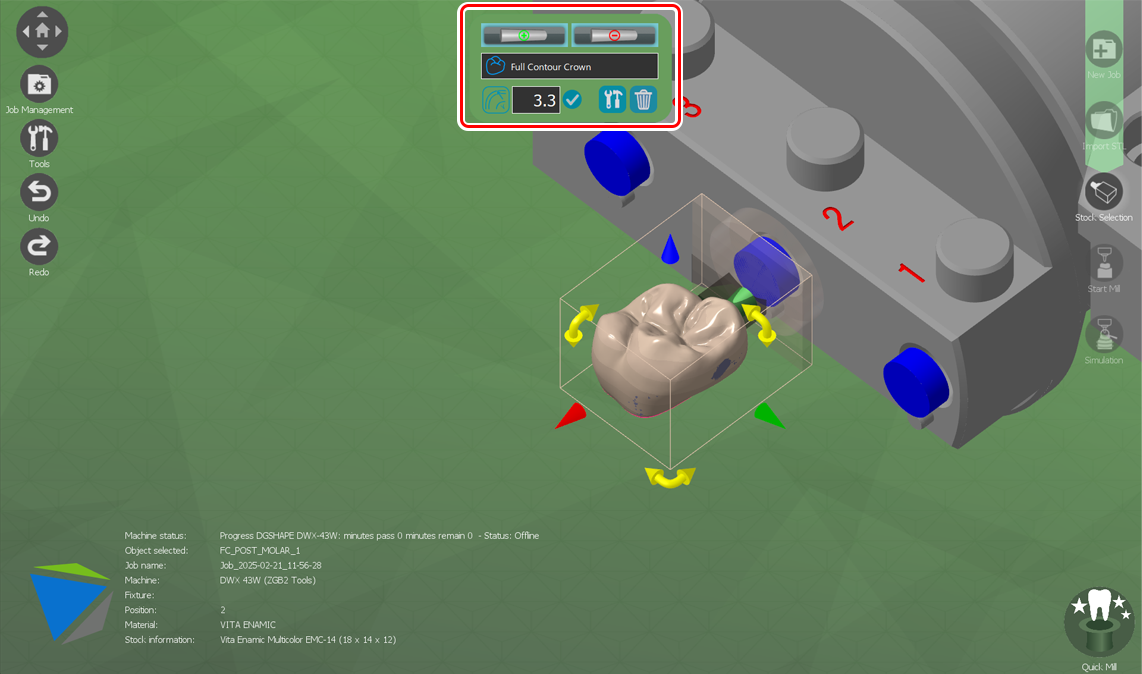
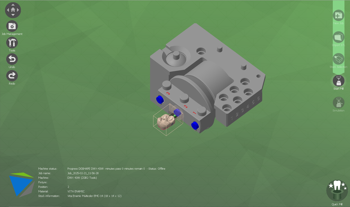
Placing the Dental Prosthesis
After selecting the stock, perform final adjustments as necessary during the dental prosthesis placement step.
Starting Cutting
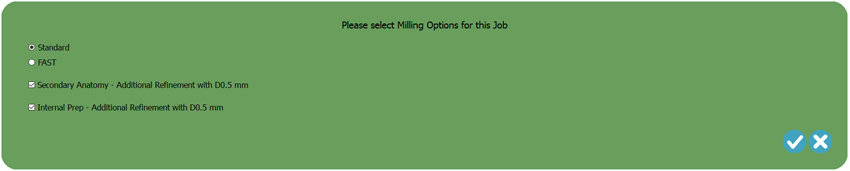
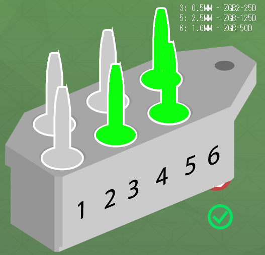
This tool table is displayed to call your attention to the cutting bur used in this job. A different material may require a specific cutting bur for the optimal cutting conditions, and this information may change from one material to the next.
The first column of this tool table shows the cutting bur slot number, size of each cutting bur, and product name of the recommended cutting bur. Some milling machines can directly track the cutting bur service life from the controller. If you are using one of these machines, you can disable the cutting bur service life tracking function.
Cutting Bur Service Life Tracking by DGSHAPE CAM
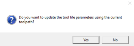
This window asks if you want to apply the cutting bur service life to the in-use cutting bur being tracked by DGSHAPE CAM. You can use this selection to exclude the current calculation from the cutting bur service life tracking. For example, this is useful when you want to perform the calculation but you do not want to execute an actual job on the milling machine.
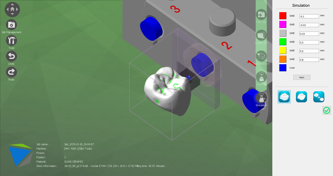
Simulating Remaining Cutting
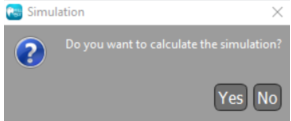
Select Yes to display a color map that indicates the cutting that may remain due to the limits of the cutting bur at the end of the calculation process. (As an example, if the cavity is designed to be narrower than the radius of the cutting bur, this material will remain without being milled by the milling machine.)
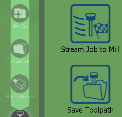
Completing the Toolpath